We may earn a commission if you make a purchase through the links on our website.
Inter-VLAN Routing Configuration 2025 Guide
UPDATED: May 12, 2023
Clients within VLANs can communicate very efficiently and securely (within their own broadcast domain), but they can never go beyond their segregated VLAN.
Inter-VLAN routing allows these clients in different VLANs to communicate with each other. They can still benefit from the network security and control provided by VLANs, but by enabling routing between them, these clients can now talk to each other, share resources, and collaborate on tasks.
However, configuring inter-VLAN routing can be a complex task. It requires a thorough understanding of networking concepts and protocols. In this configuration guide, we will provide step-by-step instructions on how to configure inter-VLAN routing for a network.
1. Inter-VLAN Communication: Using Layer 3 Devices for Routing Traffic between VLANs
VLANs (Virtual Local Area Networks) operate at Layer 2 of the OSI model. They logically group devices into separate broadcast domains and establish communication using Layer 2 addressing. One of the most remarkable advantages of VLANs is that they can segment large Layer 2 broadcast domains into smaller, isolated broadcast domains.
Using VLANs to separate broadcast domains in large switching networks ensure that only clients within the same VLANs can talk to each other— thus improving security and performance. For instance, VLAN_1 (Finance) clients (within a specific IP subnet) can only talk to other VLAN_1 clients regardless of their location, but they cannot communicate with VLAN_2 (Engineering) clients. In that case, VLAN_1 and VLAN_2 belong to separate broadcast domains and different subnets.
But what if clients across different VLANs want to communicate with each other?
Clients on different VLANs need routing to communicate with each other (inter-VLAN communication). To make clients within separate broadcast domains talk to each other, they require an external device with Layer 3 capabilities to route IP traffic. A router or Layer 3 switch allows traffic to flow freely between different VLANs in a network.
Note: Layer 2 devices (switches) will only forward traffic between devices that belong to the same VLAN (this is done through VLAN tagging at Layer 2). Since a Layer 2 device does not accept any network configuration (Layer 3) IP address, inter-VLAN routing is impossible without a Layer 3 device.
2. Three ways to implement inter-VLAN routing
There are three ways to implement inter-VLAN routing: Legacy Inter-VLAN routing, Routing-On-a-Stick, and Layer 3 + Switch SVIs. Below is a brief description of each method, along with the pros and cons.
- Legacy Inter-VLAN routing This is the most common, easiest to implement, but less scalable inter-VLAN routing technique. It uses a router (Layer 3 device) with multiple Ethernet interfaces to interconnect each VLAN. When you use the legacy inter-VLAN routing, you assign each VLAN to a separate Ethernet interface on the router. So the router acts as a gateway between VLANs. The main disadvantage of this technique is its scalability. It becomes expensive and inefficient as the number of VLANs grows.
- Router-on-a-Stick (ROAS) Like the previous method, ROAS uses a router (Layer 3) device to forward traffic between VLANs. Still, the main difference between ROAS and legacy is that ROAS uses only one router interface to route VLAN traffic. The router's physical interface gets configuration via subinterfaces (logical interfaces), each assigned with a different VLAN id. The benefit of this approach is that each subinterface can be associated with a specific VLAN and IP address. This method overcomes the scalability challenges of the legacy inter-VLAN routing method.
- Layer 3 switch + SVIs This method is quite different from the other two. Instead of relying on a router, the “Layer 3 switch + SVIs” method uses a Layer 3 switch with switched virtual interfaces (SVIs) to route traffic between VLANs. Each configured VLAN is assigned a unique IP subnet, and the switch is then configured with SVIs for each VLAN, acting as the default gateway for the VLAN. This method is highly scalable and faster as compared to the other two. This is because all switching and routing computations happen at the hardware level. The only disadvantage is that L3 switches tend to be a lot more expensive than most L2 switches and some routers.
3. How to configure inter-VLAN routing
To illustrate the inter-VLAN routing configuration process, we will configure the Routing-On-a-Stick method.
Note: We are using a Cisco network simulator known as Boson Netsim to go through the entire process in detail. Additionally, bear in mind that the commands for configuring VLANs and inter-VLAN routers vary according to Operating System, product, and inter-VLAN configuration method.
a. Topology
We will use the following Router-on-a-Stick topology in this inter-VLAN routing configuration guide. We will configure the VLAN 10 and 20 on subnets 192.168.100.1/25 and 192.168.100.129/25, respectively. To create the Router-on-a-Stick inter-VLAN method, we need a router (configured with subinterfaces) and the necessary switches. In addition, the link connecting the switch and the router (which carries the VLAN traffic) must be configured as trunk links (with the same encapsulation).
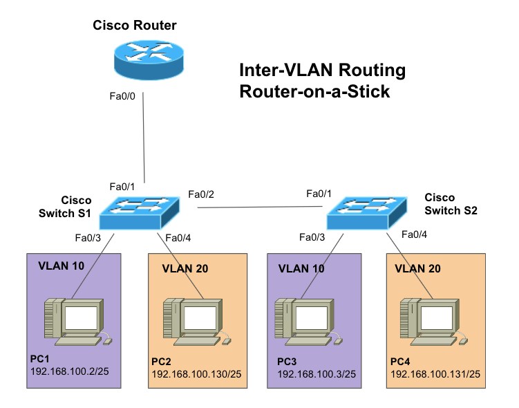
Note: We assume you have created your subnets and assigned them to each VLAN, considering scalability and performance. Each PC on each VLAN should be configured with its own subnet.
b. Preparing Configuration
Let’s start the inter-VLAN configuration by checking the current state and configuration of our switches. We’ll have to ensure no VLAN configurations (VLAN 10 and VLAN 20) exist on the switch. Also, ensure that each switch has the appropriate hostname.
- On Switch1 and Switch2, issue the following command, “show vlan.” You will see an output like the one below.
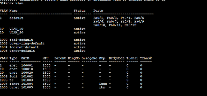
- Result: In our Switch1 (S1), no VLANs are currently configured, except the default VLAN (native VLAN) active in all the switch’s ports.
4. Configure the Switches and the PCs
In this step, we will configure the basic network connectivity between switches and PCs. In this scenario, PC1 and PC2 are connected to the Switch1, while PC3 and PC4 are connected to the Switch2. It is paramount to know that although PC1 and PC2 are connected to the same switch, the clients belong to different departments within the company.
a. Check the connection between PCs and switches
- Check the current IP configurations on all PCs and ensure they are properly set up. For example, PC1 and PC3, belonging to the same VLAN, should be in the same subnet. For this, you can issue the “ipconfig /all” on the command prompt of each PC (Windows).
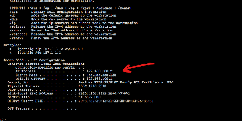
- Also, ensure that each PC is connected to the correct port on the correct switch. Although you could visually inspect the connection between the switch and the PC, you can also do the following.
- Issue an “ipconfig /all” on each computer and record the Ethernet NIC > Physical Address (MAC address).
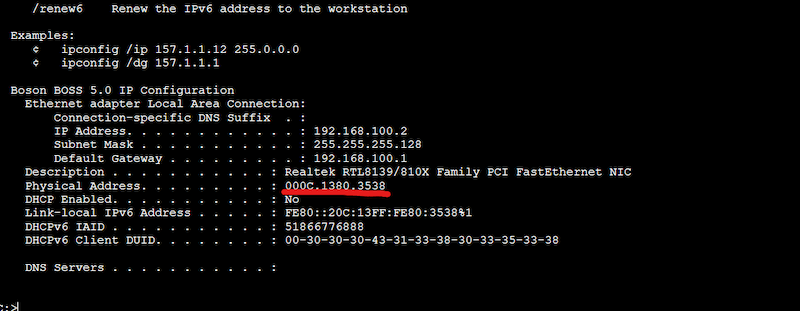
- Go to the switch and issue a “show mac address-table” to see how each MAC address is mapped to each port on the switch. For example, you can see that the below output on the switch shows a PC with MAC address 000c.1380.3538 (as shown above) is connected to port Fa0/3.

b. Configure VLANs
Now let’s configure Switch1 and Switch2 with the appropriate VLANs. As you saw from the output of “show vlan” these VLANs do not exist on the switches at the moment. Under configuration mode, use the “vlan #” command to create a VLAN and the “name NAME” command to give your VLAN a name.
Example configuration
Configuration on Switch 1 (S1)
S1# configure terminal
S1(config)# vlan 10
S1(config-vlan)# name VLAN_10
S1(config-vlan)# end
S1# configure terminal
S1(config)# vlan 20
S1(config-vlan)# name VLAN_20
S1(config-vlan)# end

After the configuration, you can issue again the “show vlan” command to see your new VLANs taking the configuration.
Configuration on Switch 2 (S2)
S2# configure terminal
S2(config)# vlan 10
S2(config-vlan)# name VLAN_10
S2(config-vlan)# end
S2# configure terminal
S2(config)# vlan 20
S2(config-vlan)# name VLAN_20
S2(config-vlan)# end
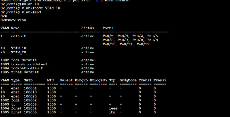
Same as with Switch1, after the configuration, issue the “show vlan” command to confirm the configuration taking effect on Switch 2.
c. Assign VLANs to the appropriate port
As you can see from the previous “show vlan” command output, VLAN_10, and VLAN_20 are already configured and active. However, these VLANs are not assigned to any port. In other words, the PCs do not belong to any VLAN yet.
To assign a VLAN to a switch port, you’ll first need to use the “switchport mode access” command to activate those interfaces into access ports. Then you will need to use the “switchport access vlan” command to assign the specific VLAN to each specific interface.
Example configuration
Configuration on Switch 1 (S1)
S1(config)# interface fastethernet 0/3
S1(config-if)# switchport mode access
S1(config-if)# switchport access vlan 10
S1(config)# interface fastethernet 0/4
S1(config-if)# switchport mode access
S1(config-if)# switchport access vlan 20
To verify your configuration, use the “show vlan brief” command. Ensure VLANs 10 and 20 are assigned to the correct ports.
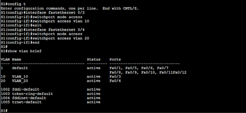
Configuration on Switch 2 (S2)
S2(config)# interface fastethernet 0/3
S2(config-if)# switchport mode access
S2(config-if)# switchport access vlan 10
S3(config)# interface fastethernet 0/4
S3(config-if)# switchport mode access
S3(config-if)# switchport access vlan 20
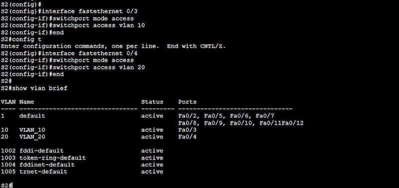
Same as with the previous configuration in Switch1, you’ll need to verify your configuration using the “show vlan brief” command. Ensure VLANs 10 and 20 are assigned to the correct ports.
d. Configuring trunk ports
Switch1 must be configured with a trunk port to Router1. The interface 0/1 on Switch 1 needs to carry the traffic from all the VLANs (in a single link). So, to allow inter-VLAN communication, you must enable trunking on the port and configure its trunking encapsulation.
Switch1(config)#interface fastethernet 0/1
Switch1(config-if)#switchport trunk encapsulation dot1q
Switch1(config-if)#switchport mode trunk

Testing your current configuration
As a test, you can try pinging from PC1 to PC2. The ping should fail because they are both in different VLANs and different subnets.

Configuring the Router
As mentioned at the beginning of the guide, communication across VLANs won’t happen across different IP networks. But by integrating Layer 3 capabilities (routing), clients within VLANs can talk to clients on other VLANs and networks.
To build the Router on a Stick diagram, we need to configure the subinterfaces on the router. To make the traffic coming from network 192.168.100.0 reach the other network 192.168.100.128 (and vice-versa), the router’s interface must know those subnets.
a. Configure Subinterfaces
To make the router handle two or more networks on a single physical interface, you’ll need to create subinterfaces.
- We will configure the subinterfaces 0/0.10 and 0/0.20 on top of interface Fastethernet 0/0, so we first must ensure this interface is enabled.
- Also, it is vital to configure the encapsulation (802.1Q) which is used for VLAN 10 and VLAN20. The command “encapsulation dot1q” is followed by the respective VLAN tag.
Router1#configure terminal
Router1(config)#interface fastethernet 0/0
Router1(config-if)#no shutdown

Router1(config-if)#interface fastethernet 0/0.10
Router1(config-subif)#ip address 192.168.100.1 255.255.255.128
Router1(config-subif)#encapsulation dot1q 10
Router1(config-subif)#interface fastethernet 0/0.20
Router1(config-subif)#ip address 192.168.100.129 255.255.255.128
Router1(config-subif)#encapsulation dot1q 20

b. Verify your configuration
- To check your previous configuration, use the “show running-config” on your router.
- Ensure your subinterfaces are appropriately configured with the encapsulation and IP address.
- As you can see on the “show running-config” output below, both subinterfaces are configured along with encapsulation and IP address.

- Issue a “show ip route” to ensure that your router has the correct IP routes in place, to handle routing from 192.168.100.0 to 192.168.100.128 (and vice-versa).

- Log into PC1, and issue a “ping” command. Try pinging a host on another VLAN— the ping should be successful.

Final Words
By following the steps outlined in this inter-VLAN configuration guide, network admins can ensure that their network is configured correctly and securely. They can take their VLANs on the switched network, bring in a router (or Layer 3 device) for forwarding traffic, and allow clients on different VLANs to talk to each other.
With proper configuration, inter-VLAN routing can help improve the functionality of a network, enabling devices on different VLANs to communicate seamlessly and securely.